7-CCNP环境.note
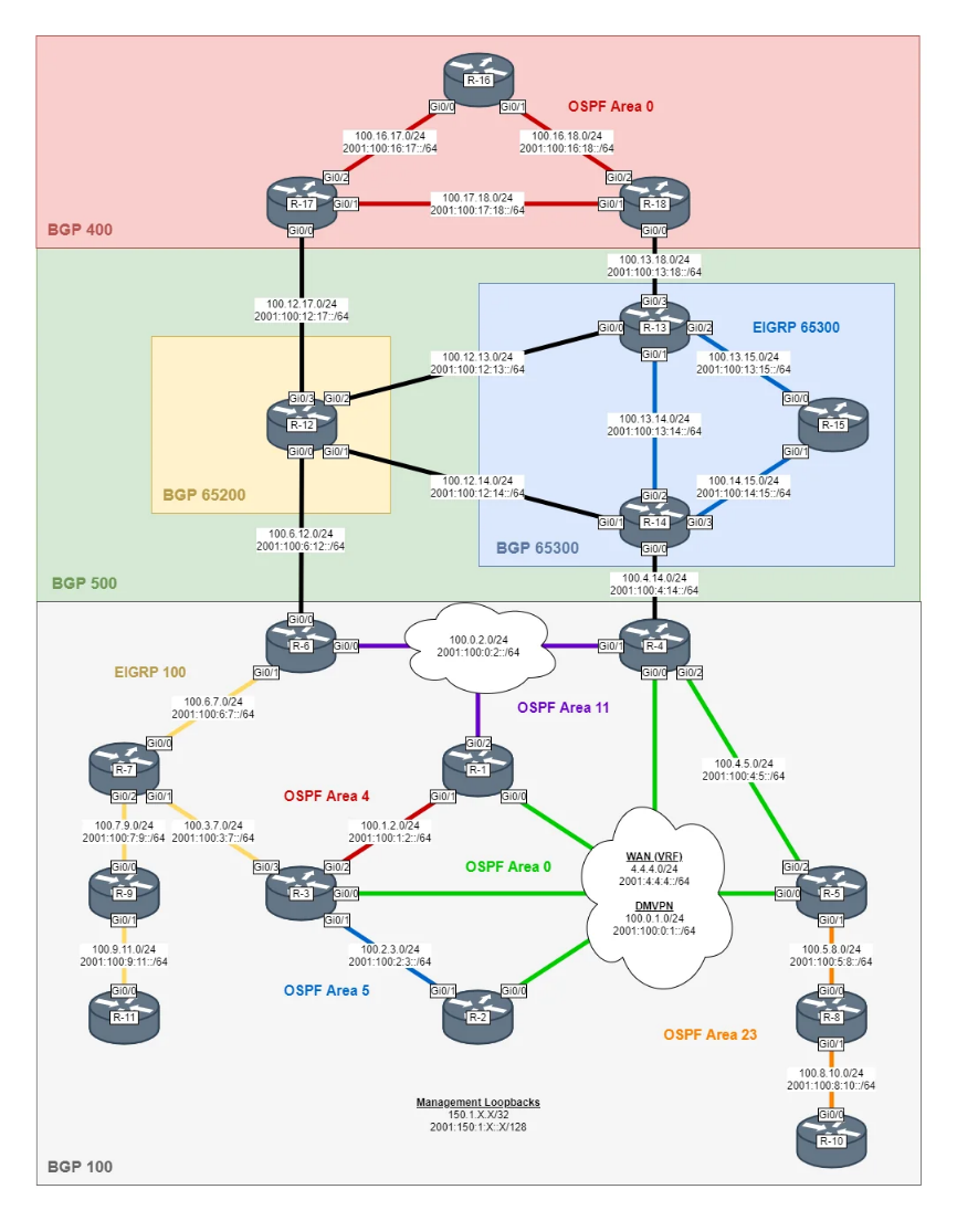
# 配置需求:
CCNP Lab Configuration Guide

1. Global Settings and VRF (Virtual Routing and Forwarding)
First, establish network isolation and the basic control plane.

Hostname and Basic Settings: Assign hostnames R-1 through R-18 to each node and configure ip domain name lab.local.

VRF Creation: Create a VRF named EXTERNAL on R-1, R-2, R-3, R-4, and R-5.

This VRF is used for WAN segment communication; both IPv4 and IPv6 address families must be activated.

Assign a unique Route Distinguisher (RD) value to each router (e.g., 1:1 for R-1, 5:1 for R-5).

Management Loopback: Create a Loopback0 interface on all routers and assign addresses in the 150.1.X.X/32 and 2001:150:1:X::X/128 ranges.

2. WAN and DMVPN Configuration
Secure connectivity between remote sites using a Virtual Private Network.

Physical Interface (WAN): Assign the GigabitEthernet0/0 interface to the EXTERNAL VRF and provide a 4.4.4.X/24 address.

DMVPN Tunnel (Tunnel0):

Common Settings: Configure tunnel mode gre multipoint, tunnel vrf EXTERNAL, ip nhrp network-id 1, and ip nhrp authentication DMVPN.

Hub (R-5): Set the OSPF priority to 255 to fix its role as the Designated Router (DR).

Spoke (R-1, R-2, R-3, R-4): Set the OSPF priority to 0 and perform NHRP mapping (ip nhrp map and nhs) to the Hub’s NBMA address (4.4.4.5).

IPv6 Support: Use ipv6 nhrp commands to apply the same mapping and NHS settings for the IPv6 address family.

3. IGP: OSPFv3 Multi-AF
Manage both IPv4 and IPv6 routing information within a single process.

OSPFv3 Process: Create router ospfv3 100 and specify a router-id X.X.X.X.

Address-Family: Activate both address-family ipv4 unicast and address-family ipv6 unicast.

Area Assignment:

Area 0 (Backbone): Assign Loopback and DMVPN tunnel interfaces.

Area 4 & 5: Assign the Ethernet segments between R-1, R-2, and R-3.

Area 11: Connection segments between R-1, R-4, and R-6.

Area 23 (NSSA): Configure the R-5, R-8, and R-10 segments as an NSSA. Specifically, R-5 propagates a default route downward using area 23 nssa default-information-originate.

4. IGP: EIGRP Named Mode
Utilize the modern EIGRP configuration method.

EIGRP Process: Create router eigrp EIGRP_NAMED.

AS Settings:

AS 100: Used by R-3, R-6, R-7, R-9, and R-11.

AS 65300: Used by R-13, R-14, and R-15.

AF and Interface Control: Set passive-interface under af-interface default, then apply no passive-interface only on interfaces where actual adjacency will be formed.

Redistribution: Perform mutual redistribution between OSPFv3 and EIGRP on R-3 and R-6. Specify the metric as: Bandwidth (1000), Delay (10), Reliability (255), Load (1), and MTU (1500).

5. BGP Hierarchy and Confederation
Finalize the design for scalability within a large-scale BGP network.

AS 100 (BGP RR):

R-4 & R-6: Act as Route Reflectors. Create INTERNAL-IPv4/IPv6 peer groups and configure route-reflector-client and next-hop-self all.

Establish iBGP peering based on Loopback addresses.

AS 500 (BGP Confederation):

Confederation ID: Use bgp confederation identifier 500 to appear as AS 500 to external peers.

Sub-AS: Assign R-12 to 65200 and R-13/14/15 to 65300.

Peers: Define connections between Sub-ASs using the bgp confederation peers command.

AS 400: R-16, R-17, and R-18 operate as a standard AS 400 and establish eBGP peering with R-12 and R-13.
# 重点:反射器层级设置:
R6 -------- R4
/ \ / | | \
R7 R1 R1 R2 R3 R5
| |
R9 R8
| |
R11 R10
R6 是 RR
client:R7、R1
R4 是 RR
client:R1、R2、R3、R5
R7 是 RR
client:R9
R5 是 RR
client:R8
R9 是 RR
client:R11
R8 是 RR
client:R10完成版: